
i3D Workbench · CAM tool Available
MillX
Upload an STL file and compute CNC milling toolpaths with configurable cutters.
MillX is a browser-based 3-axis CNC CAM tool. Load a binary STL (up to 300 MB), define up to 10 cutters in an ATC tool table (Ball Mill, End Mill, Conic, Tapered Ball Nose), chain up to three operations with RasterX, RasterY, Spiral, Concentric or Level Curve strategies, finish only the rest material left by roughing, inspect a colour-coded milling analysis and export G-code in mm or inches — one file or one per cutter — through an editable post-processor.
| Group | CAM |
|---|---|
| Status | Available |
| Input | STL (binary) |
| Output | G-code (.nc), STL (processed result) |
| Max upload | 300 MB per file |
| Runs in | Desktop browser with WebGL 2 (Chrome, Edge, Firefox) — computation on Ahaborg's C++ backend |
| Billing | Pay-per-use credits, no subscription |
| Documented in | i3D Workbench User & Reference Manual v2026.10 |
Overview
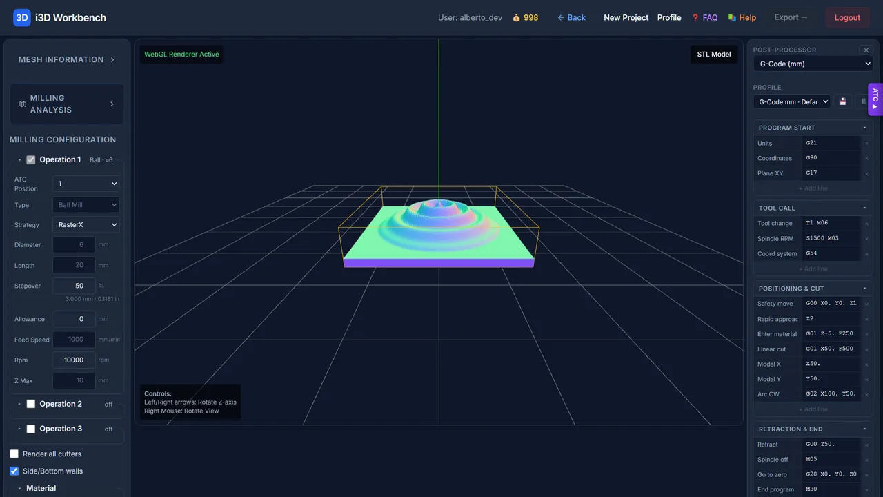
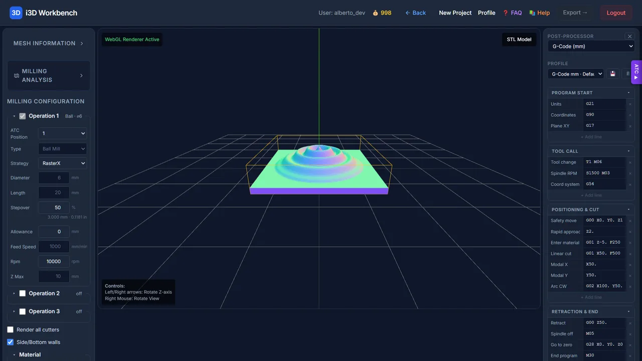
Upload a binary STL. The model is displayed in the Milling page while it is pre-uploaded to the server cache in the background. Configure up to three Operations that reference tools from the ATC tool table, define the Material stock, click Calculate to run the milling analysis, and export G-code through the post-processor.
Step by step
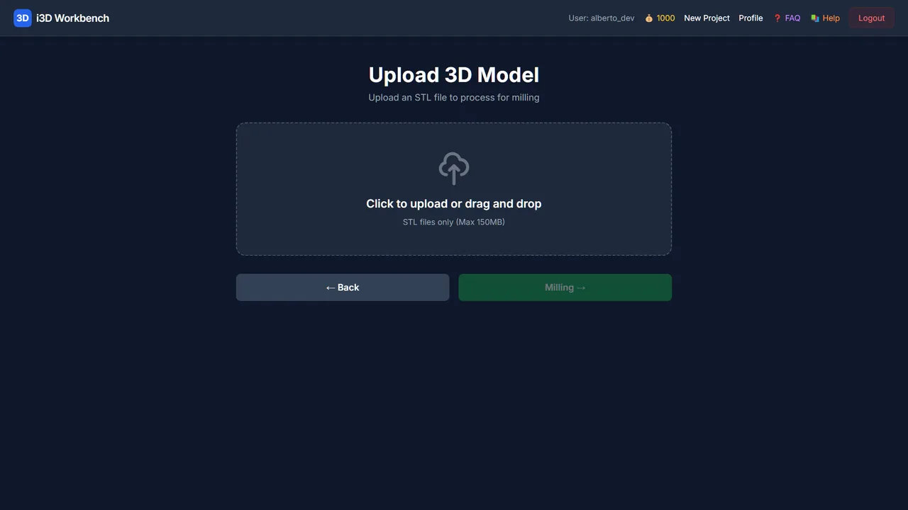
- Open MillX, select a binary STL (≤ 300 MB) and click Milling. The 3D preview loads instantly; the model is pre-uploaded to the server.
- Read Mesh Information (bounding box in mm). The Material box defaults to it — correct Width/Height/Thickness to your real stock.
- Open ATC ▶ and define your tools (up to 10 positions): type, diameter, length, feed, Z max, and angle/tip for conic tools.
- Configure Operation 1 (roughing): ATC position, Strategy, Stepover, Allowance, Rpm. Enable Operation 2/3 for finishing passes with a smaller tool and 0 allowance.
- Tick Rest Material so finishing only cuts what roughing left, and Render all cutters to preview every operation.
- Click Calculate. A progress bar shows the server analysis; press 5 to see the analysis bitmap on the model.
- Review the Post-Processor (program start, tool call, positioning & cut, retraction & end), then Export GCODE (one file, or one per cutter) and optionally Export STL.
- Open the G-code in NC Viewer before machining.
Controls
Upload step
| Control | Range / values | Default | What it does |
|---|---|---|---|
| STL file | binary STL · ≤ 300 MB | — | After upload you are redirected to the Milling page automatically, and the model is pre-uploaded to the C++ cache in the background so Calculate starts instantly. |
Mesh Information
Read-only panel with the model bounding box (X/Y/Z ranges and overall size in mm), plus the ZMap resolution, Z range, cut depth and triangle count after a calculation.
Operations (1–3)
Each operation is a collapsible box (e.g. roughing + finishing). Operation 1 is always enabled; enable 2 and 3 with their checkboxes. The header badge summarizes the tool. Tool-shape fields (Type, Diameter, Length, Feed Speed, Z Max, Angle, Tip D2) are read-only here — inherited from the ATC position.
| Control | Range / values | Default | What it does |
|---|---|---|---|
| ATC Position | 1 – 10 | 1 | Which slot of the ATC tool table this operation uses. Changing it pulls in that tool’s geometry. |
| Strategy | RasterX · RasterY · Spiral · Concentric · Level Curve | RasterX | Per-operation toolpath pattern. |
| Stepover (%) | — | 50 | Lateral step between passes as a percentage of tool diameter. Lower = finer finish, longer time. The real step (diameter × stepover / 100) is shown in mm and inches. |
| Allowance (mm) | — | 0 | Stock-to-leave / extra material kept on the surface (e.g. for a later finishing pass). |
| Rpm | — | 10000 | Spindle speed for this operation (rev/min). |
ATC — Tool Table
Open the ATC ▶ panel (Automatic Tool Changer) to define up to 10 tool positions. Operations reference these positions, so a tool is defined once and reused.
| Control | Range / values | Default | What it does |
|---|---|---|---|
| Type | Ball Mill · End Mill · Conic · Tapered Ball Nose | — | Ball (spherical — curved surfaces), End (flat — flat areas/corners), Conic (tapered — V-grooves/engraving), Tapered Ball Nose (tapered with rounded tip). |
| Diameter / Length / Feed / Z Max | — | 6 mm / 20 mm / 1000 mm·min⁻¹ / 10 mm | Tool diameter, cutting length, feed speed and maximum Z depth. |
| Angle (°) & Tip D2 (mm) | — | — | Taper half-angle and tip diameter. Only active for Conic / Tapered Ball Nose — disabled (sent as 0) for Ball / End mills. |
Material
| Control | Range / values | Default | What it does |
|---|---|---|---|
| Width / Height / Thickness (mm) | — | model bounding box | Stock block. Defaults to the model’s bounding box; override any value for the session. A wireframe box representing the stock is always drawn around the part. |
Job options
| Control | Range / values | Default | What it does |
|---|---|---|---|
| Render all cutters | — | off | Preview/compute every enabled operation together instead of one at a time. |
| Side/Bottom walls | — | on | Include the stock side and bottom walls in the analysis/visualization. |
| Rest Material | — | off | Compute remaining material so finishing passes only cut what roughing left. |
| Generate multiple files (one per cutter) | — | off | On export, output one G-code file per operation instead of a single combined file. |
Post-Processor (right panel)
| Control | Range / values | Default | What it does |
|---|---|---|---|
| Processor | G-Code (mm) · G-Code (inches) | — | Output flavor used by Export GCODE. |
| Profile | — | — | Named set of sections (💾 save / 🗑 delete). |
| Program start | — | G21 · G90 · G17 | Units, coordinates, plane. |
| Tool call | — | T1 M06 · S1500 M03 · G54 | Tool change, spindle, coordinate system. |
| Positioning & cut | — | G00 X Y Z · Z2. · G01 Z-5. F250 · G01 X50. F500 · X50. · Y50. · G02 … | Safety move, rapid approach, enter material, linear cut, modal X/Y, arc CW templates. |
| Retraction & end | — | G00 Z50. · M05 · G28 X0 Y0 Z0 · M30 | Retract, spindle off, go to zero, end program. |
Visualization
Switch shading with number keys: 1 PBR (realistic gray) · 2 Matcap · 3 Curvature · 4 Normal map colours (default) · 5 Milling analysis bitmap (after Calculate: gray = normal, red = high zone, green = low zone). Left/Right arrows rotate around Z; right mouse rotates the view. An amber wireframe shows the Material stock block.
Actions
| Control | Range / values | Default | What it does |
|---|---|---|---|
| Calculate | — | — | Sends operations + ATC tools + material to the server for the milling analysis (SSE progress bar; auto-recalculates on parameter changes). Disabled while processing. |
| Export GCODE | — | — | Generates and downloads the G-code via the post-processor. Enabled only after a successful Calculate; one or multiple files per the option above. |
| Export STL | — | — | Downloads the processed result mesh. Available after Calculate. |
Tips & tricks — MillX
- Roughing: End Mill or large Ball Mill, Stepover 40–50 %, Allowance 0.3–0.5 mm. Finishing: Ball Mill, Stepover 8–12 %, Allowance 0, Rest Material on. That alone halves machining time compared with a single fine pass.
- Choose RasterX/RasterY for reliefs (switch axis between roughing and finishing to erase scallops), Spiral/Concentric for round parts, Level Curve for steep walls.
- Make the Material Thickness the real stock thickness, not the model height — the analysis uses it to decide how deep the walls go.
- Z Max of the tool must exceed Material thickness minus the model floor, or the bottom of the relief is never reached.
- Conic / Tapered tools: Tip D2 is the diameter that actually cuts the floor; a 0.2 mm tip at 10 % stepover means a 0.02 mm step — raise the stepover or the job takes hours.
- Press 5 after Calculate and look for red zones: they are areas the current tool cannot reach (too large). Add a finishing operation with a smaller tool.
- Export one file per cutter when your machine has no automatic tool changer; load each file after the manual tool change.
- ATC positions and post-processor profiles are saved per user, so build your tool library once.
Troubleshooting
MillX does not process automatically the first time.
The 3D preview is client-side. The first server analysis runs when you click Calculate so you can configure operations first; afterwards changes auto-recalculate (debounced).
Export GCODE / Export STL are disabled.
They activate only after a successful Calculate — the server needs a processed session before it can emit G-code or the result mesh.
“STL not yet uploaded to server”.
The background pre-upload is still running (large file or slow link). Wait for the status line and click Calculate again.
Where did the “Reduction Factor” slider go?
It was replaced by the Material box (Width / Height / Thickness), which defines the stock block drawn as a wireframe.
Works well with
Tools that chain with MillX — see the workflows.